
South DOTLAS Plus
Software
- GNSS Fieldwork: SurvStar
- Fieldwork Partner: smartphone recommended (instead of regular data logger)
- SLAM Fieldwork: SurvStar
- SLAM Pre-proces: RobotSLAM Engine
-
Description
Why DotLas Plus?
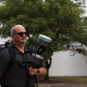
Literally, DotLas is a highly integrated device capable of point (= dot) measurement and laser scanning. Thatʼs how this new compound word DotLas came. And Plus here actually refers to something extra, merged applications. By combining the immense power from the existing 2 core technologies in geo-spatial society, it features amazing versatility, and intends to challenge some complex environments where conventional GNSS RTK cannot satisfy. Therefore, it resets the benchmark of GNSS RTK hybrid models and tops itself as the supreme masterpiece in the industry.
Why 1+1>2 Is True?
① Magicalc = Magic + calculation (Positioning while Satellites Unlocked)
With DotLas Plus, itʼs possible to obtain coordinate information in the way of Mixed Solution in GNSS-unfriendly or even GNSS-denied areas. The SLAM trajectory will help to reverse compute the positional result and continue point measurements when satellites are unlocked. The Magicalc accuracy mainly depends on the unlocked duration, SLAM trajectory distance, and texture details of the new environment.
② AirMeas = Air Measurement (Contactless Measurement)
Have you heard about iPhone AirDrop? AirMeas is somewhat similar to this principle or saying. For some inaccessible zones, DotLas Plus may help to measure in the way of SLAM data capture within scanning range. Just imagine how to measure the center of the manhole cover on the ground, center of a router device installed overhead, etc. Go to the point in pano image overlaid with colorized point cloud, and you will obtain the coordinate automatically instead of reaching there physically.
③ Super Stake-out
On the market, AR stake-out has been applied to more and more RTK receiver models. Generally speaking, AR stake-out goes with visual aided methodology. While AirMeas is to measure the unknown point that is inaccessible, Super Stake-out helps to reach the known point in the way of pano image overlaid with colorized point cloud, which is a powerful reverse application of AirMeas.
About Fixed Solution & Mixed Solution
Fixed Solution means that the GNSS RTK rover and its allocated base station can simultaneously track at least five satellites in common, and then
the rover keeps receiving differential corrections from the base station, which is already widely acknowledged in the geospatial community.
Mixed Solution refers to a reverse computed result scientifically derived from the time synchronization of SLAM trajectory and earlier positional records, which well interprets the Mix&Match Combo. By unlocking the combined power of GNSS+SLAM, it sets out A Brand New Concept to the Industry indeed.
Specification
| GENERAL | Model | DotLas Plus |
| Series | RobotSLAM | |
| Functionality | SLAM-based RTK, RTK-based SLAM, and merged applications all-round | |
| Type | GNSS RTK hybrid supreme | |
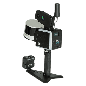
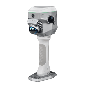
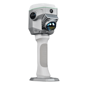
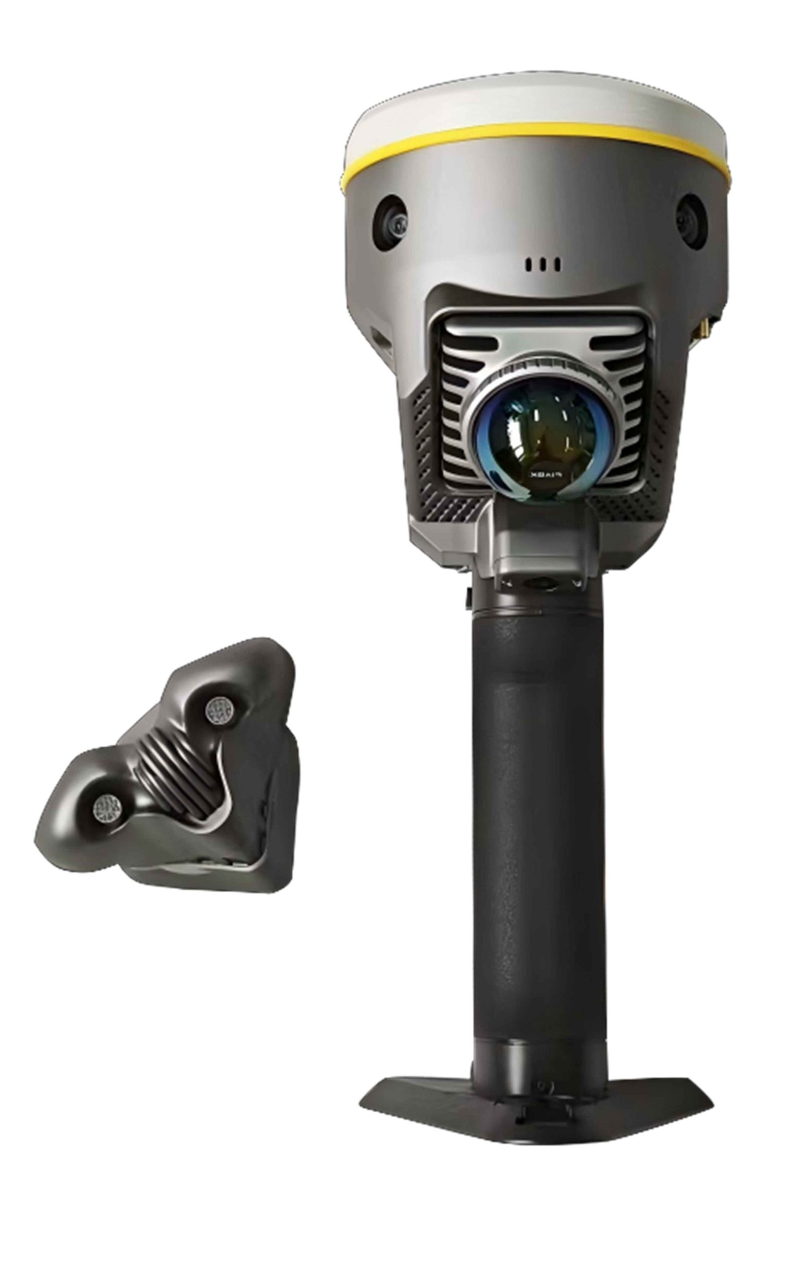
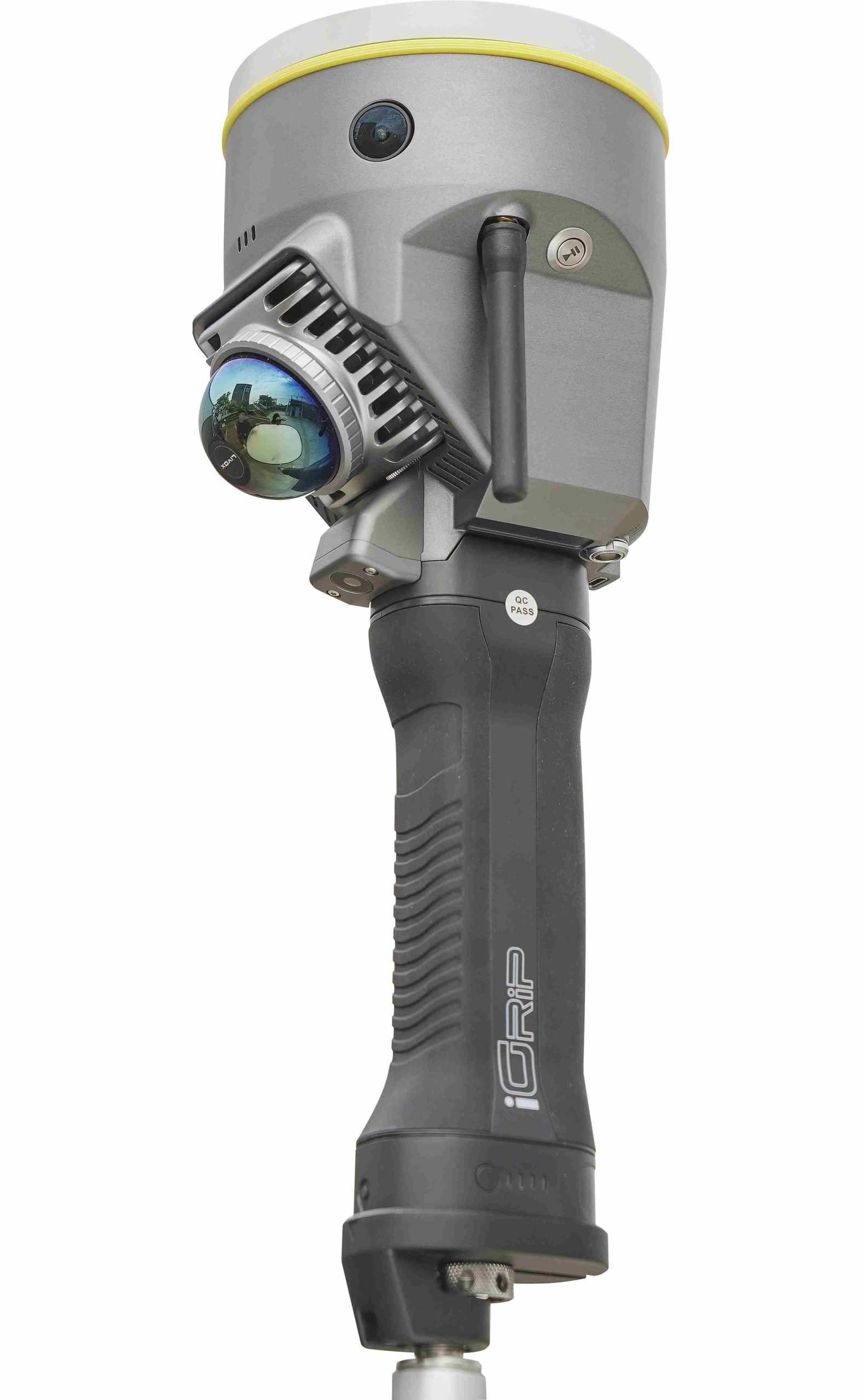
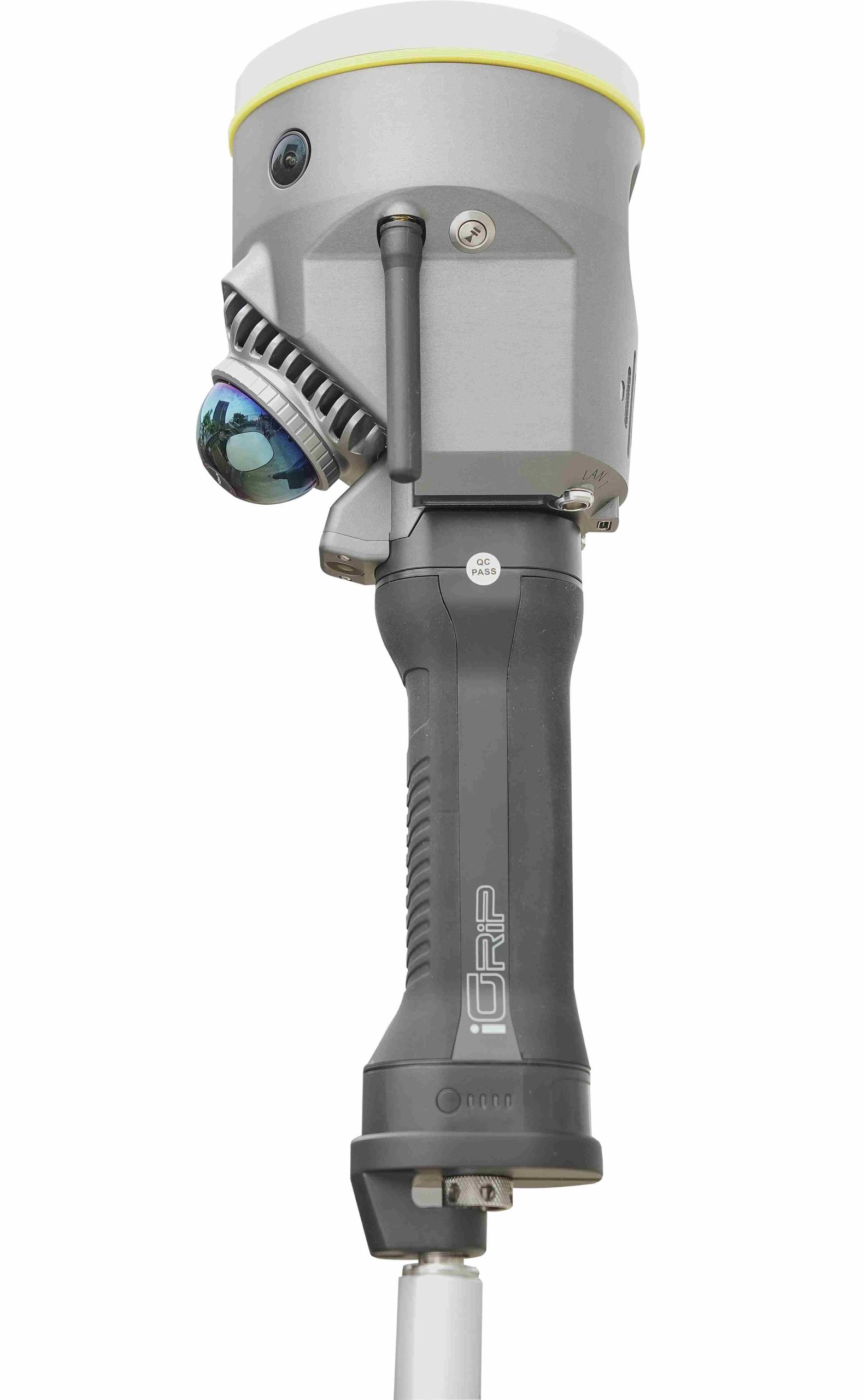
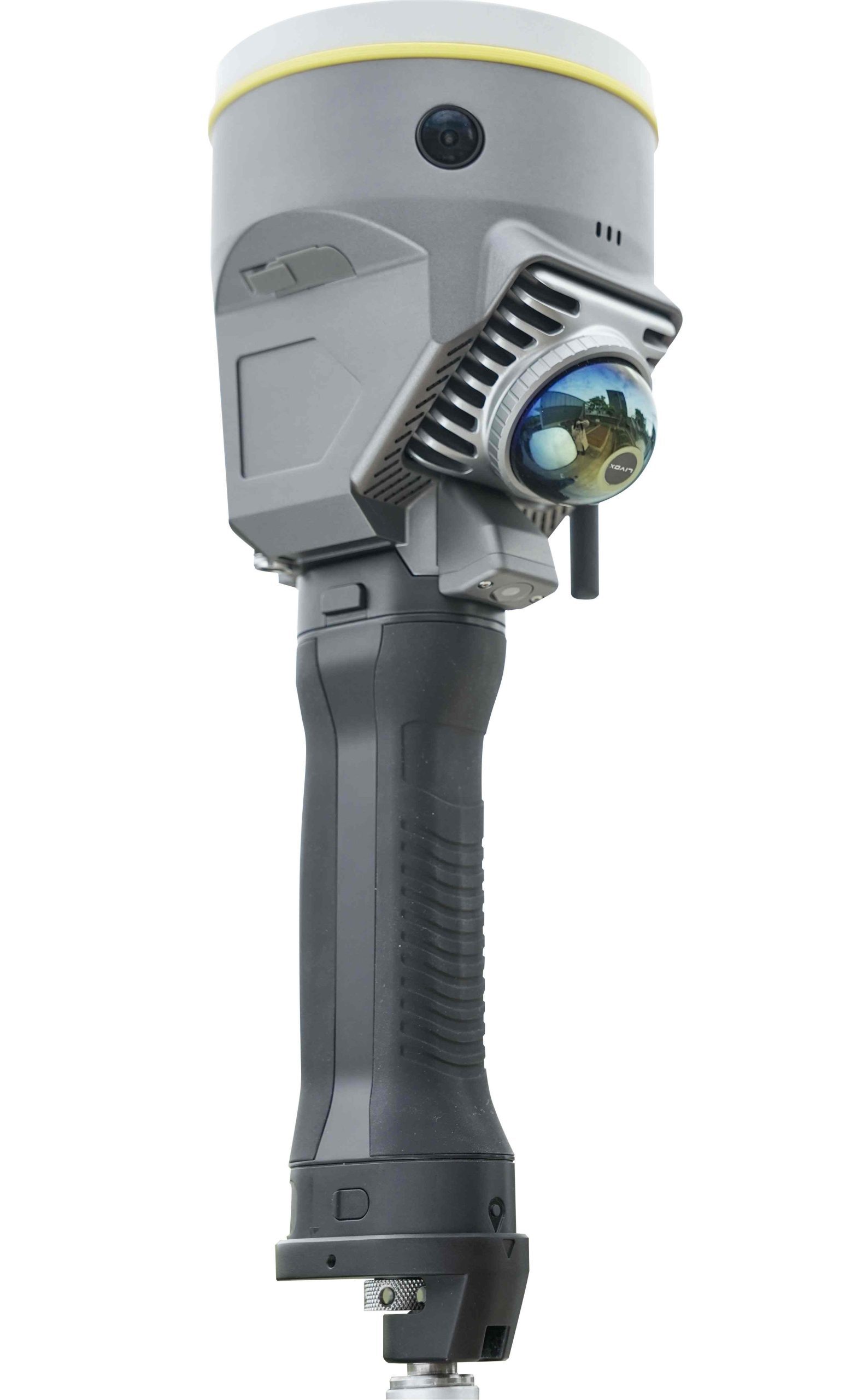
| Component | built in with GNSS mainboard, SLAM scanner, camera lenses, temperature sensor, IMU, smartwatch-like LED screen, etc. | |
| PHYSICAL | Dimension | 120x120x340 mm (LxWxH) |
| Net Weight | 1.4 kg (battery handgrip excluded); 1.8 kg (battery handgrip inclusive) | |
| Camera (for SLAM) | horizontal and forward, pixel size 2.0 μm, FOV 210°x120°, resolution 10 MP in total (5 MP x2), imaging effect best up to 20 MP | |
| Camera (for GNSS) | downward, resolution 2 MP x1, FOV 75° | |
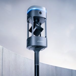
| Laser Scanner | Livox Mid-360 built in, 3D mixed solid-state sensor, 40 channels | |
| Data Download | Type-C and Ethernet interfacing | |
| LEMO Interfacing | LAN1 (7-pin) and LAN2 (9-pin), for debugging and RS232 data transfer, etc. | |
| Temperature Sensor | built in, intelligent variable frequency temperature control, realtime monitors and regulates device temperature | |
| IMU Module | built in for GNSS, and supports tilt survey option, Linux OS | |
| LED Screen | smartwatch-like, round face, 1.39-inch, resolution 454×454 | |
| Wi-Fi Module | built in and serves as a Wi-Fi hotspot source, accessible to any smart device for configuration | |
| Network Telecom | SIM card slot built in, Nano SIM | |
| Radio Wireless | radio antenna interfacing SMA | |
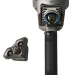
| ELECTRICAL | Power Supply | battery handgrip unit, model: iGrip, 50 Wh, 3500 mAh |
| Endurance | ≥2 hours | |
| Power Consumption | 26 W | |
| Charging | charging time 2 hours, type-C recharge, max. current 3 A | |
| Input Voltage | nominal 14.4 V | |
| Power Output | charging 30 W max. current 5 A max. | |
| ENVIRONMENTAL | Working Temperature | -20 ~ 50 ℃ |
| Storage Temperature | -20 ~ 60 ℃ | |
| Operating Humidity | 80% non-condensing | |
| Ingress Protection | IP64 rating according to IEC 60529 | |
| COMMUNICATION | Screen Operation | touch operation, for mode setting and status display |
| Wi-Fi Datalink | device may access to Wi-Fi for transmit and receive differential corrections | |
| Web Interaction | Web UI management platform built in, accessible to device for relatime monitoring device status and device configuration via Wi-Fi and USB | |
| Audio Messaging | iVoice smart audio technology on board, for smart status broadcasting and voice instructions | |
| Voice Language | supports Chinese, English, Korean, Russian, Portuguese, Spanish, Turkish as default | |
| Radio Datalink | RX radio module built in, working frequency 410-470 MHz, protocol Farlink, SOUTH, TrimTalk450S, ZHD, HUACE | |
| Bluetooth | BT4.2 (BR/EDR+BLE) standard automatic Bluetooth pairing between device and controller by touch (NFC module on board | |
| NFC Wireless | is needed for controller side) | |
| WLAN | 802.11b/g/n standard | |
| DATA MANAGEMENT | Data Transfer | USB, FTP, and HTTP |
| Data Storage | SSD 4 GB (for GNSS) and 512 GB (for SLAM) built in, extendable to 1 TB max. | |
| Data Format | Static: South STH, Rinex2, Rinex3.02, etc. | |
| Differential: RTCM3.0, RTCM3.2 input and output | ||
| GPS output: NMEA0183, PJK plane coordinate, binary code | ||
| Network module: VRS, FKP, MAC, N-Trip | ||
| SOFTWARE | GNSS Fieldwork | SurvStar |
| Fieldwork Partner | smartphone recommended (instead of regular data logger) | |
| SLAM Fieldwork | SurvStar | |
| SLAM Pre-proces | RobotSLAM Engine |
Note: all information above is subject to change without any prior notice.